8.1.1. Swd2vtk User’s Guide
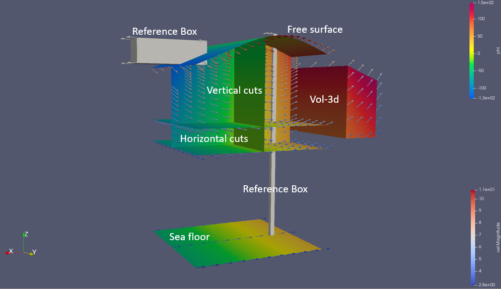
Various objects swd2vtk may construct. These objects and related fields are explained below.
Contents
8.1.1.1. In a nutshell
The program swd2vtk is provided for making advanced three-dimensional visualization of SWD wave kinematics. The program is a command line tool. The usage is outlined in this diagram
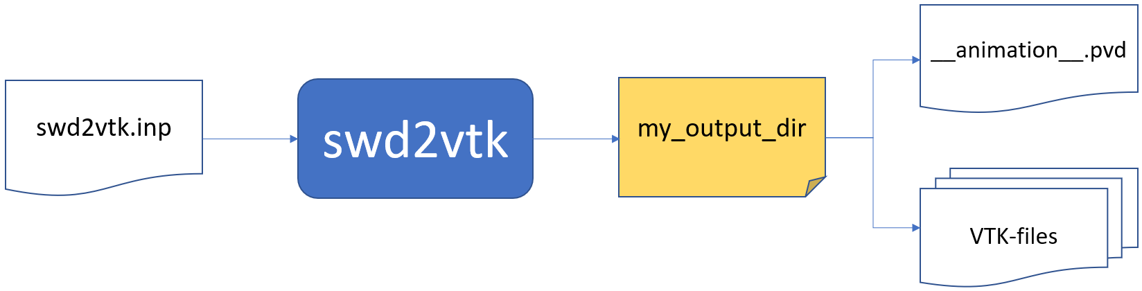
Based on the contents of a text file, typical called swd2vtk.inp, swd2vtk will generate a set
of VTK files in a user specified subdirectory. In that directory there is a file __animation__.pvd
containing links to the relevant VTK files for different time steps. This file can be loaded into
.e.g. ParaView for making advanced animations.
The input file could be named anything but in this document we apply the name swd2vtk.inp.
If swd2vtk is in your path you can execute it using the command:
swd2vtk swd2vtk.inp
The VTK files produced are of the new generation format (XML) and not the legacy VTK format. swd2vtk may produce ascii, binary or raw VTK files.
Other relevant post-processing tools for the VTK-files are e.g. Mayavi and VTK for python.
Note
The computational effort and file storage requirements for running swd2vtk depends significantly on the user specified spatial and temporal resolution.
8.1.1.2. Example input file
The parameters in this example file are explained in the next sections.
8.1.1.3. Coordinate systems
Swd2vtk has an application specific coordinate system
\((\bar{x},\bar{y},\bar{z})\) related to the SWD coordinate system \((x,y,z)\) as described
in the theory section of this documentation. The related constructor parameters are specified
in the input file swd2vtk.inp.
To make it possible to simulate the SWD wave field near a ship moving with a constant speed
along the \(\bar{x}\)-axis, an
animation coordinate system is introduced. This system is moving with a constant speed
speedx along the \(\bar{x}\)-axis and coincide with the application coordinate system at
the application time \(\bar{t}=0\). All locations of objects specified in swd2vtk.inp and
in the resulting VTK-files are with respect to the animation coordinate system.
All kinematics presented in the VTK files (e.g. \(\frac{\partial\phi}{\partial \bar{t}}\) and particle
velocities) are with respect to the earth fixed application coordinate system.
The reference speed speedx may take any real value. Negative values indicates that the ‘ship’ is
moving in the negative x-direction.
8.1.1.4. Input parameters
All input values in swd2vtk.inp are specified in a Fortran namelist called swd2vtk as
demonstrated in the header of the example file.
Consequently, comments may be inserted anywhere using the tag “!”.
Input variables may be specified in any order and in any column.
Parameters not specified in swd2vtk.inp
will keep a default value. Default values are given in the tables below.
Characters are enclosed in quotes and logical/bools are specified using the letters T and F
without quotes.
Fortran namelist can be parsed and generated from Python using the PyPI package f90nml. This package may also convert between YAML and namelist.
The following parameters are specified in swd2vtk.inp.
8.1.1.4.2. Time and speed parameters
parameter |
type |
description |
|---|---|---|
tstart |
real |
Start animation output at application time = tstart [s]. (Default: tstart=0.0) |
tend |
real |
End animation output at application time = tend [s]. (No default) |
dt |
real |
Applied time step in animation output [s]. (No default) |
speedx |
real |
Speed of animation coordinates relative to earth fixed application sys. [m/s].
Default is speedx=0.0
|
time_fmt |
char*15 |
Fortran format specifier for time string. E.g. time_fmt = ‘(f0.3)’ (three digits)
Default: time_fmt = ‘(f0.3)’
|
8.1.1.4.3. SWD constructor parameters
parameter |
type |
description |
|---|---|---|
x0_swd |
real |
SWD constructor parameter x0. (Default: x0_swd = 0.0) |
y0_swd |
real |
SWD constructor parameter y0. (Default: y0_swd = 0.0) |
t0_swd |
real |
SWD constructor parameter t0. (Default: t0_swd = 0.0) |
beta_swd |
real |
SWD constructor parameter beta. (Default: beta_swd = 0.0) |
impl_swd |
integer |
SWD constructor parameter impl. (Default: impl_swd = 0) |
norder_swd |
integer |
SWD constructor parameter norder. (Default: norder_swd = 0) |
ipol_swd |
integer |
SWD constructor parameter ipol. (Default: ipol_swd = 0) |
nsumx_swd |
integer |
SWD constructor parameter nsumx. (Default: nsumx_swd = -1) |
nsumy_swd |
integer |
SWD constructor parameter nsumy. (Default: nsumy_swd = -1) |
dc_bias_swd |
logical |
SWD constructor parameter dc_bias. T or F. (Default: dc_bias_swd = F) |
rho_swd |
real |
SWD constructor parameter rho. (Default: rho_swd = 1025.0)
Pressure will have unit meter water column if rho_swd = 0.102.
|
8.1.1.4.4. Requested scalar fields
To decide which scalar fields should be evaluated and included in the VTK files
we apply T/F flags representing True or False in the namelist. These fields are
calculated using the SWD class methods pressure(), phi() , phi_t(),
stream(), elev(), elev_t(), grad_elev(),
grad_phi_2nd() and grad_elev_2nd().
parameter |
type |
description |
|---|---|---|
scl_prs |
logical |
Total wave pressure from |
scl_stream |
logical |
Stream function from |
scl_phi |
logical |
Velocity potential \(\phi\) from |
scl_phi_t |
logical |
\(\frac{\partial \phi}{\partial \bar{t}}\) from |
scl_phi_xx |
logical |
\(\frac{\partial^2 \phi}{\partial \bar{x}^2}\) from |
scl_phi_xy |
logical |
\(\frac{\partial^2 \phi}{\partial \bar{x}\partial \bar{y}}\) from |
scl_phi_xz |
logical |
\(\frac{\partial^2 \phi}{\partial \bar{x}\partial \bar{z}}\) from |
scl_phi_yy |
logical |
\(\frac{\partial^2 \phi}{\partial \bar{y}^2}\) from |
scl_phi_yz |
logical |
\(\frac{\partial^2 \phi}{\partial \bar{y}\partial \bar{z}}\) from |
scl_phi_zz |
logical |
\(\frac{\partial^2 \phi}{\partial \bar{z}^2}\) from |
scl_elev |
logical |
Wave elevation \(\zeta\) from |
scl_elev_t |
logical |
\(\frac{\partial \zeta}{\partial \bar{t}}\) from |
scl_elev_x |
logical |
\(\frac{\partial \zeta}{\partial \bar{x}}\) from |
scl_elev_y |
logical |
\(\frac{\partial \zeta}{\partial \bar{y}}\) from |
scl_elev_xx |
logical |
\(\frac{\partial^2 \zeta}{\partial \bar{x}^2}\) from |
scl_elev_xy |
logical |
\(\frac{\partial^2 \zeta}{\partial \bar{x}\partial \bar{y}}\) from |
scl_elev_yy |
logical |
\(\frac{\partial^2 \zeta}{\partial \bar{y}^2}\) from |
8.1.1.4.5. Requested vector fields
To decide which vector fields should be evaluated and included in the VTK files
we apply T/F flags representing True or False in the namelist.
These fields are calculated using the SWD class methods
grad_phi(), acc_euler() and acc_particle().
parameter |
type |
description |
|---|---|---|
vec_vel |
logical |
Particle velocity from |
vec_acc_e |
logical |
Local acceleration from |
vec_acc_p |
logical |
Particle acceleration from |
8.1.1.4.6. Free-surface sheet
Using the variable if_free_surf the user may request a thin sheet representing the instant position of the free-surface in a rectangular horizontal region.
The center of this region is specified by the parameters (x=`xc_free_surf`, y=`yc_free_surf`) with respect to the animation coordinate system. The length of this region along the application x-dir is xlen_free_surf and ylen_free_surf in the y-dir.
The number of evenly distributed cells in the x-dir and y-dir are npanx_free_surf and npany_free_surf respectively. For each vertex in this horizontal grid the instant wave elevation will be calculated. These wave elevations defines the z-location of this surface sheet.
Selected scalar and vector fields are evaluated in the cell nodes of the free-surface sheet.
parameter |
type |
description |
|---|---|---|
if_free_surf |
logical |
Flag to indicate if the free-surface sheet should be generated.
Default: if_free_surf = T
|
xc_free_surf |
real |
The x-mid-point of sheet (animation coord. system). No default. |
yc_free_surf |
real |
The y-mid-point of sheet (animation coord. system). No default. |
xlen_free_surf |
real |
The length of free-surface sheet in x-dir (animation coord. system).
No default.
|
ylen_free_surf |
real |
The length of free-surface sheet in y-dir (animation coord. system).
No default.
|
npanx_free_surf |
integer |
Number of cells (>0) in x-dir (animation coord. system). No default. |
npany_free_surf |
integer |
Number of cells (>0) in y-dir (animation coord. system). No default. |
8.1.1.4.7. Sea floor sheet
In case of finite depth simulations a sheet displaying the local bathymetry can be generated. This feature is automatically turned off in case of infinite water depth.
Using the variable if_floor the user may request a thin sheet representing the sea floor in a rectangular horizontal region.
The center of this region is specified by the parameters (x=`xc_floor`, y=`yc_floor`) with respect to the animation coordinate system. The length of this region along the application x-dir is xlen_floor and ylen_floor in the y-dir.
The number of evenly distributed cells in the x-dir and y-dir are npanx_floor and npany_floor respectively. For each vertex in this horizontal grid the local bathymetry is calculated. These values defines the z-location of the sea floor.
Selected scalar and vector fields are evaluated in the nodes of the sea floor sheet.
parameter |
type |
description |
|---|---|---|
if_floor |
logical |
Flag to indicate if the sea floor sheet should be generated.
Automatic F in case of infinite depth. Default: if_floor = T
|
xc_floor |
real |
The x-mid-point of sheet (animation coord. system). No default. |
yc_floor |
real |
The y-mid-point of sheet (animation coord. system). No default. |
xlen_floor |
real |
The length of sea floor sheet in x-dir (animation coord. system).
No default.
|
ylen_floor |
real |
The length of sea floor sheet in y-dir (animation coord. system).
No default.
|
npanx_floor |
integer |
Number of cells (>0) in x-dir (animation coord. system). No default. |
npany_floor |
integer |
Number of cells (>0) in y-dir (animation coord. system). No default. |
8.1.1.4.8. 3D-volume block
Using the variable if_vol3d the user may request if a 3D structured domain of hexahedrons should be generated.
The extent of this domain is rectangular in the horizontal plane. In the vertical direction it occupies the space from z=zmin_vol3d up to the instant free-surface. The horizontal center of the domain is at (x=`xc_vol3d`, y=`yc_vol3d`). The horizontal length of this domain along the application x-dir is xlen_vol3d and ylen_vol3d in the y-dir.
The number of cells in the x-dir, y-dir and z-dir are npanx_vol3d, npany_vol3d and npanz_vol3d respectively. In the horizontal directions the cells are evenly spaced. In the vertical direction it is possible to have smaller cells closer to the free surface. The density of cells are controlled using the expansion factor z_exp_vol3d.
Selected scalar and vector fields are evaluated in the nodes of each cell.
parameter |
type |
description |
|---|---|---|
if_vol3d |
logical |
Flag to indicate if a 3D solid volume block should be generated.
Default: if_vol3d = F
|
xc_vol3d |
real |
The x-mid-point of the volume (animation coord. system). No default. |
yc_vol3d |
real |
The y-mid-point of the volume (animation coord. system). No default. |
zmin_vol3d |
real |
The lowest z-value of the block (animation coord. system). No default. |
xlen_vol3d |
real |
The length of the block in x-dir (animation coord. system).
No default.
|
ylen_vol3d |
real |
The length of the block in y-dir (animation coord. system).
No default.
|
npanx_vol3d |
integer |
Number of cells (>0) in x-dir. No default. |
npany_vol3d |
integer |
Number of cells (>0) in y-dir. No default. |
npanz_vol3d |
integer |
Number of cells (>0) in z-dir. No default. |
z_exp_vol3d |
real |
Expansion ratio for cell heights in z-dir. (1.0 = constant spacing)
Default: z_exp_vol3d = 1.1 (cell height for cell below increase 10%)
|
8.1.1.4.9. Vertical cuts
The user may specify a number (n_vcut) of vertical cut-planes from z=zmin_vcut up to the free-surface. The horizontal extent of this sheet is len_vcut. The horizontal center of each sheet is specified by the parameters (x=`xc_vcut`, y=`yc_vcut`) with respect to the animation coordinate system. The angle between the cut plane and the yz-plane is beta_vcut.
The number(s) of cells in the horizontal and vertical directions are npanxy_vcut and npanz_vcut, respectively. The spacing is constant in the horizontal direction. In the vertical direction it is possible to have smaller cells closer to the free surface. The density of cells are controlled using the expansion factor z_exp_vcut.
Because there may be more than one vertical cut, the *_vcut parameters above are arrays. Consequently, if you specify n_vcut=3 you may specify
yc_vcut = 0.0 10.0 20.0 ! Specify for all cuts in one line...
in the input file. Similar for the other parameters denoted with the tag (A) in the table below. As an alternative, in accordance with the Fortran namelist convention, you may specify:
yc_vcut(1) = 0.0    ! One-based indexing
yc_vcut(2) = 10.0
yc_vcut(3) = 20.0
Selected scalar and vector fields are evaluated in the cell nodes of each vertical cut.
parameter |
type |
description |
|---|---|---|
n_vcut |
integer |
Number of vertical cuts to define. Default: n_vcut = 0 |
xc_vcut |
real (A) |
The x-mid-point(s) of vertical cuts (animation coord. system).
No default.
|
yc_vcut |
real (A) |
The y-mid-point(s) of vertical cuts (animation coord. system).
No default.
|
zmin_vcut |
real (A) |
The lowest z-value(s) of vertical cut(s) (animation coord. system).
No default.
|
len_vcut |
real (A) |
The horizontal length(s) of vertical cuts. No default.
|
beta_vcut |
real (A) |
The angle(s) between cut plane(s) and the yz-plane [deg]. No default.
e.g. 0.0 => yz plane, 90.0 => xz plane
|
npanxy_vcut |
integer (A) |
Number of cells (>0) in the horizontal direction for each cut.
No default.
|
npanz_vcut |
integer (A) |
Number of cells (>0) in z-dir. No default. |
z_exp_vcut |
real (A) |
Expansion ratio for cell heights in z-dir. (1.0 = constant spacing)
Default: z_exp_vcut = 1.1 (cell height for cell below increase 10%)
|
8.1.1.4.10. Horizontal cuts
The user may specify a number (n_hcut) of horizontal rectangular cut-planes.
The center of each cut plane is specified by the parameters (x=`xc_hcut`, y=`yc_hcut`) at z=z_hcut with respect to the animation coordinate system. The length of this region along the application x-dir is xlen_hcut and ylen_hcut in the y-dir.
The number(s) of evenly distributed cells in the x-dir and y-dir, are npanx_hcut and npany_hcut, respectively.
Because there may be more than one horizontal cut, the *_hcut parameters above are arrays. Consequently, if you specify n_hcut=3 you may specify
z_hcut = -5.0 -10.0 -15.0 ! Specify for all cuts in one line...
in the input file. Similar for the other parameters denoted with the tag (A) in the table below. As an alternative, in accordance with the Fortran namelist convention, you may specify:
z_hcut(1) = -5.0    ! One-based indexing
z_hcut(2) = -10.0
z_hcut(3) = -15.0
Selected scalar and vector fields are evaluated in the cell nodes of each horizontal cut.
parameter |
type |
description |
|---|---|---|
n_hcut |
integer |
Number of horizontal cuts to define. Default: n_hcut = 0 |
xc_hcut |
real (A) |
The x-mid-point(s) of horizontal cuts (animation coord. system).
No default.
|
yc_hcut |
real (A) |
The y-mid-point(s) of horizontal cuts (animation coord. system).
No default.
|
z_hcut |
real (A) |
The constant z-value(s) of horizontal cut(s) (animation coord. system).
No default.
|
xlen_hcut |
real (A) |
The length of horizontal cut(s) in x-dir (animation coord. system).
No default.
|
ylen_hcut |
real (A) |
The length of horizontal cut(s) in y-dir (animation coord. system).
No default.
|
npanx_hcut |
integer (A) |
Number of cells (>0) in x-dir (animation coord. system). No default. |
npany_hcut |
integer (A) |
Number of cells (>0) in y-dir (animation coord. system). No default. |
8.1.1.4.11. Virtual boxes
The user may specify a number (n_box) of virtual boxes (rectangular cuboids) for visual references in the animations.
These boxes may visualize the location and extent of ships, wave probes etc. to better see relevant wave profiles at different time instances. These boxes do not move relative to the animation coordinate system.
The virtual boxes do not affect the simulated wave kinematics. Wave kinematics is not evaluated on virtual box surfaces.
The center of each virtual box is specified by the parameters (x=`xc_box`, y=`yc_box`, z=`zc_box`) with respect to the animation coordinate system. The dimensions of each box in the x-dir, y-dir and z-dir are xlen_box, ylen_box and zlen_box, respectively.
Because there may be more than one box, the *_box parameters above are arrays. Consequently, if you set n_box=3 you may specify
xc_box = -50.0 0.0 50.0 ! Specify for all boxes in one line...
in the input file. Similar for the other parameters denoted with the tag (A) in the table below. As an alternative, in accordance with the Fortran namelist convention, you may specify:
xc_box(1) = -50.0    ! One-based indexing
xc_box(2) =   0.0
xc_box(3) =  50.0
parameter |
type |
description |
|---|---|---|
n_box |
integer |
Number of virtual boxes to define. Default: n_box = 0 |
xc_box |
real (A) |
The x-mid-point(s) of boxes (animation coord. system). No default. |
yc_box |
real (A) |
The y-mid-point(s) of boxes (animation coord. system). No default. |
zc_box |
real (A) |
The z-mid-point(s) of boxes (animation coord. system). No default. |
xlen_box |
real (A) |
The length of boxes in x-dir (animation coord. system). No default. |
ylen_box |
real (A) |
The length of boxes in y-dir (animation coord. system). No default. |
zlen_box |
real (A) |
The length of boxes in z-dir (animation coord. system). No default. |
8.1.1.5. Download and Installation
Binary distributions of swd2vtk, for Windows and Linux, can be downloaded from the release tab of the GitHub repository spectral_wave_data.
Note
To run swd2vtk on windows you need to download and install the latest version of the Intel Redistributable Package for Fortran 2020. The Intel redistributable contains required DLLs. If you already have a very recent Intel Fortran compiler installed you may skip this installation.
8.1.1.6. Acknowledgement
swd2vtk applies the library VTKFortran by Stefano Zaghi (INSEAN) under the MIT-license.